
In my last blog post I have written about how we finally completed the DC measurement reporter for our Green Metrics Tool.
In the last days we have looked at reducing the variance of the ATX powerlanes and finding out if swapping out the resistors for more stable current measurement resistors can improve the measurement.
Here are the results!
Used hardware
- We are now using Isabellenhütte PBV 0,005 Ohm current measurement resistors
- We have swapped out all the wiring and replaced it with new wiring that has matching resistances for every connection.
- The lines connecting the two inner terminals of the current resistors are with 0.9 Ohm wires
- The lines connectiong the two outer terminals are connected with 1.7 Ohm wires.
- Accuracy on the measurement is +/- 0.1 Ohms
Adding the remaining lines on the ATX connector
In the PoC of our last blog post we have concentrated on the six 12 V power lines of the ATX connector. The connector however features 4 more slots, where one slot however is not connected with the PSU.
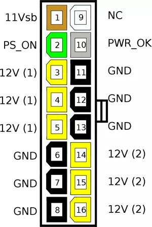
For overview, here is a diagram of the pin assignment (credits to Wan Hung Lo Electronics)
As visible in the image the remaining 3 lanes are:
- PS_ON: This is pulled to high / low to activate the PSU from the mainboard
- PWR_OK: This can tell the PSU if the voltage level is ok
- 11Vsb: This is the Standby Power for stuff like WakeOnLan etc. and needed power to trigger PS_ON
So for our case, since our PicoLog HDR ADC-24 has only 8 differential inputs we have to drop at least one of these lines.
We measured the PS_ON pin and got a minimal reading of ~ 20 mV out of it. This pin is only really needed to be connected on boot and seems to be irrelevant for the measurments. As well in functionality as also in the power that it consumes.
So we could included the 11Vsb and the PWR_OK in our measurements.
However when looking at the screenshots of the readouts you see that they do not really contribute to the total power. This was expected for PWR_OK (apart from an error case maybe), but may not be the case for the 11Vsb.
Depending on what device you have attached and how the mainboard wiring is done there could be a power draw on this line.
However in our internal measurements we have not seen any power draw over that line and since it is kept on a stable voltage it clashes with the behaviour of our input channel. The input channel was constantly giving out a stable reading of a negative voltage over the current resistor although no current was flowing.
To quickly falsify our assumption we checked with our AC power readings on a simple wall socket power meter and the results where better in line with what we saw when the channel was left out.
We suppose this is a sampling problem with the channel as it carries no current, but still shows a voltage reading, which should not be the case.
Therefore we opted for leaving the 11Vsb channel out.
Updating the time measurements
All analysis is now done on the System Under Test directly. That means all timestamps are derived from the same clocksource.
Currently we use the PicoLog 6.2.4 AppImage to get the measuremens as the Linux libraries for Ubuntu are broken.
Running that AppImage gives us an overhead in the measurement of around 0.3 - 0.5 W.
You can compare the measurements here:
- Measurement with PicoLog AppImage running on System Under Test
- Measurement with PicoLog AppImage running on external machine
Analysing the 12 V rails
As suggested in our previous post the 12 V lines are internally not all wired to the same channel, but are split in two rails.
This is also seen in modern sytems, where the P4 connector can provide a second 12 V rail for energy hungry CPUs.
Why Fujitsu made the decision to split every 12 V rail in three cables we might never know though :).
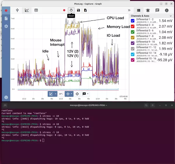
By making a short stress test with stress -c 10 and stress -m 10 we see that the one rail gets
more loaded on a CPU intensive load and the other rail more on a memory intensive load.
They are so distinguishable that by just looking at rail #1 one can tell if the DRAM is accessed. However the direction the other way round does not hold. Rail #2 is also loaded, cause obvioulsy the CPU has to feed the DRAM.
Nevertheless this insight might pose an interesting starting point for an algorithmic or ML detection of what kind of load is happening.
Summary of new setup
The total energy consumed with the new setup is very close to the old measurement with the old resistors.
Compare the readings on:
This is because we do not look at single lanes, but average the voltages per channel and then add them up to get the energy over time. Even in an imbalanced system this should give us the total energy.
However the new resistors have less variance and therefore pose a better accurarcy per channel (if interesting) and also are better in heat resistance, which will make the measurement more stable over time.
The next step is to falsify with an AC reading, which we will do in conjuction with the replication of the measurements from the Blauer Engel Team over the next weeks. After that we will integrate the harddisk into the measurement to close the gap of uncertainty further.
If you want to falsify our DC measurements or get to know how to make them work in your setup please shoot me an email to [email protected] !